Updated: 12-01-2021
The first tool that I used to create N-Body Simulation was WebGPU, which is a JavaScript API for accelerated graphics and computing in web browsers. (Still in development) WebGPU is an easily accessible tool for GPU programming since it doesn’t have a hardware requirement like Nvidia’s CUDA. This was my first time getting into GPU programming, so I was very excited!
I will be referring to specific file names from my code, so take a look at them if you are interested! Github Link
0a. General Structure
Here is a general structure of my implementation of WebGPU to simulate the N-Body particle simulation
- Get all variables needed for WebGPU API calls.
- Create render and compute pipelines. They will hook up instructions from
.wgsl files
- Create and initialize a Float32Array that stores the properties of all particles. (position and velocity)
- Create Buffer and BindGroups for the compute pipeline. They will hook up a binding to particle data that can be used during computation.
- Start computation (N-Body) on particles.
- Start rendering of particles.
- Measure performance (FPS) to see the duration of Steps 5 and 6.
- Repeat 5-7.
0b. How to use WebGPU
There are currently two ways (that I know of) to use WebGPU.
Google Chrome Canary
Since WebGPU is still in development, it is available in Google Chrome Canary. Google Chrome Canary is an environment for developers that allow new features, flags, and APIs to be used and tested. After downloading Google Chrome Canary, make sure to enable the flag Unsafe WebGPU by directing to chrome://flags
Chrome Origin Trial
Another way to use WebGPU is to register for a token through Chrome Origin Trial. This way, WebGPU can be used in regular Google Chrome. After registering, I inserted the token in index.html for my local server.
index.html
<meta http-equiv="origin-trial" content="INSERT_TOKEN">
In order to see if the WebGPU is working properly, you can open Chrome’s Inspect window -> Application -> Frames -> top, then scroll down to find Origin Trials. Here, you will find WebGPU with “Enabled” sign if the inserted token is working properly.
1. Getting Variables
There are four variables that I will need to initialize. I went through this link to learn about them.
- Adapter (GPUAdapter): An implementation of WebGPU on the system. It will be used to get GPUDevice.
- Device (GPUDevice): The logical instantiation of an adapter, top-level interface through which WebGPU interfaces are created. It will be used to call WebGPU API calls.
- Context (webgpu): Context of canvas that can be configured for rendering the particles.
- Format: Specifies order of components, bits per component, and data type for the component. It will be used for context configuration.
bgra8unorm means blue, green, red, and alpha 8 bits per components unsigned normalized data type
2. Render and Compute Pipeline
In my project, I will be using .wgsl files to create functions that can be used by render and compute pipelines. Following is my code for creating a render pipeline:
mainWebGPU.ts
const spriteShaderModule = device.createShaderModule({ code: spriteWGSL });
const renderPipeline = device.createRenderPipeline({
    vertex: {
        module: spriteShaderModule,
        entryPoint: 'vert_main',
        buffers: [
          {
            // vertex buffer
            arrayStride: 4 * 4,
            stepMode: 'vertex',
            attributes: [
              {
                // vertex positions
                shaderLocation: 0,
                offset: 0,
                format: 'float32x2',
              },
            ],
          },
        ],
      },
      fragment: {
        module: spriteShaderModule,
        entryPoint: 'frag_main',
        targets: [
          {
            format: format as GPUTextureFormat
          },
        ],
      },
      primitive: {
        topology: 'point-list'
      },
})
sprite.wgsl
[[stage(vertex)]]
fn vert_main([[location(0)]] particlePos : vec2<f32>) -> [[builtin(position)]] vec4<f32> {
    return vec4<f32>(particlePos, 0.0, 1.0);
}

[[stage(fragment)]]
fn frag_main() -> [[location(0)]] vec4<f32> {
        return vec4<f32>(1.0, 1.0, 1.0, 1.0);
}
The use of render pipeline is to determine if the shape and color of an object that I want to create. Since I will be creating particles, which is the most simple shape, my code ended up being pretty straightforward. The variable renderPipeline creates a render pipeline using the information from spriteWGSL. It will use the information of vertex (size), and the information of fragment (color) to render objects to canvas.
The WebGPU provides 5 primitive topologies that can determine the general shape of rendered objects. (point-list, line-list, line-strip, triangle-list, triangle-strip) This is pretty similiar to WebGL, so it will be easier to understand if you are familiar with WebGL.
point-list: Used for drawing a series of pointsline-list Used for drawing line segments, but not connected to each other.line-strip Used for drawing line segmenest and connected to each other.triangle-list Used for drawing triangles.triangle-strip Used for drawing triangles that are connected to each other.
2.1. Rotating Objects
Since I will be using only particles in my project, I didn’t have to worry about rotating my objects to make sure that they are facing toward the direction that they are moving in. If you are wondering how that can be done, here is an example that I found: Source
main.ts
vertex: {
  module: spriteShaderModule,
  entryPoint: 'vert_main',
  buffers: [
    {
      // instanced particles buffer
      arrayStride: 4 * 4,
      stepMode: 'instance',
      attributes: [
        {
          // instance position
          shaderLocation: 0,
          offset: 0,
          format: 'float32x2',
        },
        {
          // instance velocity
          shaderLocation: 1,
          offset: 2 * 4,
          format: 'float32x2',
        },
      ],
    },
    {
      // vertex buffer
      arrayStride: 2 * 4,
      stepMode: 'vertex',
      attributes: [
        {
          // vertex positions
          shaderLocation: 2,
          offset: 0,
          format: 'float32x2',
        },
      ],
    },
  ],
}
sprite.wgsl
[[stage(vertex)]]
fn vert_main([[location(0)]] a_particlePos : vec2<f32>,
             [[location(1)]] a_particleVel : vec2<f32>,
             [[location(2)]] a_pos : vec2<f32>) -> [[builtin(position)]] vec4<f32> {
  let angle = -atan2(a_particleVel.x, a_particleVel.y);
  let pos = vec2<f32>(
      (a_pos.x * cos(angle)) - (a_pos.y * sin(angle)),
      (a_pos.x * sin(angle)) + (a_pos.y * cos(angle)));
  return vec4<f32>(pos + a_particlePos, 0.0, 1.0);
}
At first, you can definitely see how the code is more complicated. Under the attributes:, the shaderLocation and offset are defined to let the function vert-main know where the position, velocity of particles can be found in the array that will store all the particles’ properties. In this example, the particles’ properties get stored in Float32Array. Each particle will take up 4 indices in the array: positionX, positionY, velocityX, and velocityY. Since Float32Array uses 4 bytes per element, the offset of velocity value needs to be 2 * 4 to make sure that values are being read in the correct places.
2.2. Size of Objects
This was also something that I didn’t have to worry about, since particles have fixed size. If you are wondering how changing the size of objects can be done here is an example of determining the size of triangle-list topology: Source
main.ts
const vertexBufferData = new Float32Array([
  -0.01, -0.02, 0.01,
  -0.02, 0.0, 0.02,
]);

const spriteVertexBuffer = device.createBuffer({
  size: vertexBufferData.byteLength,
  usage: GPUBufferUsage.VERTEX,
  mappedAtCreation: true,
});
new Float32Array(spriteVertexBuffer.getMappedRange()).set(vertexBufferData);
spriteVertexBuffer.unmap();
While it looks like variable vertexBufferData is holding 6 values, those 6 values are actually representing 3 vertices:
- First vertex with the value of -0.01 (x) and -0.02(y)
- Second vertex with the value of 0.01 (x) and -0.02(y)
- Third vertex with the value of 0.0 (x) and 0.02(y)
Hopefully, you can visualize a triangle by plugging those 3 vertices!
Let’s say you want to make the triangle a little wider, then you would want to replace x values of the first (e.g. -0.01 -> -0.02) and the second vertex. (e.g. 0.01 -> 0.02)
Lastly, when you are rendering objects, make sure to call this command to set your vertex buffer to the encoder:
main.ts
const passEncoder = commandEncoder.beginRenderPass(renderPassDescriptor);
...
passEncoder.setVertexBuffer(1, spriteVertexBuffer);
Source
3. Storing Particles Data
Here, I will be creating a Float32Array with the size of Number of Particles * 4. Each particle will take up 4 indices from the array. (PosX, PosY, VelX, VelY) Then, I will go through the array and initialize the positions of each particle with random values.
const initialParticleData = new Float32Array(numParticles * 4);
for (let i = 0; i < numParticles; ++i) {
    initialParticleData[4 * i + 0] = 2 * (Math.random() - 0.5); // posX
    initialParticleData[4 * i + 1] = 2 * (Math.random() - 0.5); // posY
    initialParticleData[4 * i + 2] = 0; // velX
    initialParticleData[4 * i + 3] = 0; // velY
}
The reason why I use Float32Array is due to how WebGPU contains WebGL application, which requires vectors and matrices to be passed as a TypedArray (e.g. Float32Array).
4. Buffer and BindGroups
GPUBuffer is stored data that can be used in GPU operations. I will be creating a GPUBuffer with initialParticleData so the particle properties (position and velocity) can be used in GPU operations.
mainWebGPU.ts
const particleBuffers: GPUBuffer[] = new Array(2);
for (let i = 0; i < 2; i++) {
    particleBuffers[i] = device.createBuffer({
        size: initialParticleData.byteLength,
        usage: GPUBufferUsage.VERTEX | GPUBufferUsage.STORAGE,
        mappedAtCreation: true,
    });
    new Float32Array(particleBuffers[i].getMappedRange()).set(
        initialParticleData
    );
    particleBuffers[i].unmap();
}
Here, I will be specifying the size and usage of GPUBuffer, and set mappedAtCreation: true, allowing me to set the buffer’s initial data. After that, I use .getMappedRange() function to initialize the buffer’s data with initialParticleData. After completion of the .getMappedRange() function, the function .unmap() is required to be called to allow the buffer’s contents to be used by GPU again. I will be explaining why I created an array of GPUBuffer with the size of 2 at the end of talking of GPUBindGroup.
GPUBindGroup is used for bounding a set of resources together in a group. In my case, I will be using GPUBindGroup to bound the simParamBuffer (Buffer that holds parameter variables used in computation), and particleBuffers. The GPUBindGroup will be created similar to how pipelines were created:
mainWebGPU.ts
const particleBindGroups: GPUBindGroup[] = new Array(2);
for (let i = 0; i < 2; i++) {
    particleBindGroups[i] = device.createBindGroup({
        layout: computePipeline.getBindGroupLayout(0),
        entries: [
            {
                binding: 0,
                resource: {
                    buffer: simParamBuffer
                }
            },
            {
                binding: 1,
                resource: {
                    buffer: particleBuffers[i],
                    offset: 0,
                    size: initialParticleData.byteLength
                }
            },
            {
                binding: 2,
                resource: {
                    buffer: particleBuffers[(i + 1) % 2],
                    offset: 0,
                    size: initialParticleData.byteLength
                }
            }
        ]
    });
}
updateSprite.wgsl
[[binding(0), group(0)]] var<uniform> params : SimParams;
[[binding(1), group(0)]] var<storage, read> particlesA : Particles;
[[binding(2), group(0)]] var<storage, read_write> particlesB : Particles;
First, calling the compute pipeline’s .getBindGroupLayout(0) will assign the layout number as 0. This is why in updateSprite.wgsl, each variable has group(0) header. Next, I assign the binding number (0-2) of each buffer, allowing each variable in updateSprite.wgsl to be used during computation. Binding 1 will contain a buffer for reading purposes while binding 2 will contain a buffer for reading and writing purposes. This means that the binding 2 buffer contains the “main particles” that are going to get the new location after computation while the binding 1 buffer contains the previous location value to be used for the computation of “main particles”. The reason why I still need the previous location value is to prevent any of the threads to use the new location value in part of the computation. For example, if I want to compute a new location of a particle at index 4, I still need to do the computation with the previous values of particles at indices 0, 1, 2, and 3 instead of their new values.
5. Particle Computation
Since I have finished setting up variables, buffers, and bindgroups, it is ready to move onto the main loop of the code. There will be a function called frame() that will be repeated infinitely, and the function frame() will handle computing particles’ new locations, rendering particles with their new locations, and measuring performance.
The function main() from updateSprite.wgsl will handle the particle computation with bindings that I have set up in Step 4. Here is the pseudocode of the computation:
updateSprite.wgsl
function main() {
    Initialize variables.
    Go through all the particles in particlesA. (contain previous location and velocity values)
        Handle computation.
    Write back the new location and velocity.
}
Back to the mainWebGPU.ts file, the following lines in function frame() will handle Command Encoding for computation:
mainWebGPU.ts
const commandEncoder = device.createCommandEncoder();
{
    const passEncoder = commandEncoder.beginComputePass();
    passEncoder.setPipeline(computePipeline);
    passEncoder.setBindGroup(0, particleBindGroups[t % 2]);
    passEncoder.dispatch(256);
    passEncoder.endPass();
}
The function .createCommandEncoder() creates a GPUCommandEncoder that can be either encoded a compute pass or render pass. In this case, I will be calling .beginComputePass() to set the command encoder to be encoded as a compute pass. Then, I will set the pipeline and bind group to the encoder and finally call .dispatch() to begin working with the registered pipeline and bind group. The maximum workgroup size is 256, so I have decided to dispatch work with maximum workgroup size. Note: I will do more experiments and research on workgroups to see what number of workgroups gives the best result.
6. Rendering Particles
Before rendering in particles, I have to initialize a GPURenderPassDescriptor to be used for encoding a render pass.
mainWebGPU.ts
const textureView = context.getCurrentTexture().createView();
const renderPassDescriptor: GPURenderPassDescriptor = {
    colorAttachments: [
        {
            view: textureView,
            loadValue: { r: 0.0, g: 0.0, b: 0.0, a: 1.0 }, //background color
            storeOp: 'store'
        }
    ]
}
Inside the GPURenderPassDescriptor, I will be setting properties of colorAttachments that will be visible when executing the render pass. The loadValue will accept 2 types: (1)GPULoadOp: Load operation to be performed on view prior to executing the render pass. (2) GPUColor: Indicates the value to clear view prior to executing the render pass. Here, I am using GPUColor to set the background color of view. Before executing the render pass (rendering in particles), the renderPassDescriptor will load black background color first. Finally, the storeOp indicates the store operation to perform on view after executing the render pass. Note: The official WebGPU website does not explain what each storeOp (store, discard) does. I will do more research and update it here.
Next, I will be calling .beginRenderPass() with the Command Encoder that I created before computation.
mainWebGPU.ts
    const passEncoder = commandEncoder.beginRenderPass(renderPassDescriptor);
    passEncoder.setPipeline(renderPipeline);
    passEncoder.setVertexBuffer(0, particleBuffers[(t+1)%2]);
    passEncoder.draw(numParticles);
    passEncoder.endPass();
Similar to Step 5, I will be passing the renderPassDescriptor that I created, setting the pipeline, and setting the vertex buffer. Here, you will be able to notice that I am setting the vertex buffer with particleBuffers[(t+1)%2]. This was done to match with the particleBuffer that compute pass used to write the new location of particles. For example, if t = 0, compute pass will use particleBindGroups[0], which will be using particleBuffer[1] to write the new locations of particles. Then, the render pass will use particleBuffer[(0+1)%2] = particleBuffer[1] to render the particles with their new locations. Finally, I will be calling .draw() function to draw primitives (point-list) with the encoder.
This part is pretty simple, I used JavaScript’s performance.now() to see how long compute and render pass took.
Here is some data (Average FPS for 10000 frames) that I collected:
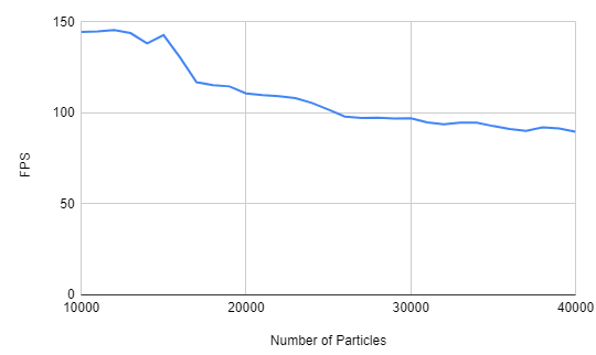
Before 10000 particles, the average FPS was capped at 144. This may be due to hardware restriction, since my monitor has a refresh rate of 144 Hz. After 10000 particles, you can see that the average FPS is slowly decreasing. While the simulation was running, I have noticed that FPS was very unstable after 10000 particles. (It was jumping +- 20~30 FPS) After observing my results, I came up with some questions that I can try to answer in the future:
- After going over
10000 particles, FPS became significantly unstable. Why is this happening? Does this have to do with the size of the workgroup? How come under 10000 particles resulted in stable FPS?
- Does
144 FPS has to do with any hardware restrictions? Like is the refresh rate of my monitor restricting the FPS to go over 144 FPS? Is there any way to remove this restriction?
- Similiar to Question 1, can I make any changes to pipelines, buffers, bindgroups, or command encoder to increase the performance?
Anyway, look at this cool-looking particle simulation:

My Personal Device Info:
- CPU: Intel(R) Core(TM) i7-9700k CPU @ 3.60GHz 3.60GHz
- RAM: 16.0 GB
- GPU: NVIDIA GeForce RTX 2080
- OS: Windows 10
- System Type: 64-bit, x64-based processor
Useful Links: